Em mới lượm ve chai được con desktop DELL, máy bộ. Nó không xài bộ nguồn như máy tính bình thường mà xài adapter như laptop.
Cái adapter hiếm quá chắc không tìm được. Nhưng cũng show hàng lên đây để các bác thấy, biết đâu có bác nào có thì để lại cho em.
Cái adapter đó mã là DELL DA-2

Bây giờ em muốn chế bộ nguồn thay cho adapter đó bằng nguồn atx mà không biết pinout nó như thế nào.
Lùng trên google mấy ngày thì tìm được cái này:

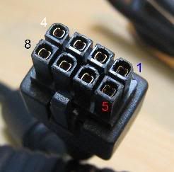
The pinout, numbered as in the picture, is:
1: N/C. Soldered to a through-hole in the adapter's PCB, but that through-hole is not connected to anything else on the PCB.
2,3,4 : +12V. Three white wires to carry the outbound current. Two meters of 16 gauge copper is about 24 mOhm, and 18 Amps through that would be about a 425 mV drop, so this adapter triples the wire, dividing the drop by three (i.e. 142 mV at max current). The three wires solder together into one big hole in the adapter's PCB.
Pin 5 : 'Trigger.' There's a pullup resistor in the brick which causes this signal to float up to a few volts. Short this line to ground, and the adapter goes from Standby (amber LED) to On (green LED).
Pins 6,7,8 : Ground. Three black 16g wires. They have to carry all that 18 A current back to the adapter, so unfortunately, this means that 'ground' inside this PC is up to 142 mV higher potential than earth. All three are soldered together into one hole in the adapter's PCB ground plane.
Em không hiểu cho lắm. Các bác dịch hộ em với
Link nguồn đây: http://www.silentpcreview.com/forums...ic.php?t=38787
Cái adapter hiếm quá chắc không tìm được. Nhưng cũng show hàng lên đây để các bác thấy, biết đâu có bác nào có thì để lại cho em.
Cái adapter đó mã là DELL DA-2

Bây giờ em muốn chế bộ nguồn thay cho adapter đó bằng nguồn atx mà không biết pinout nó như thế nào.
Lùng trên google mấy ngày thì tìm được cái này:

The pinout, numbered as in the picture, is:
1: N/C. Soldered to a through-hole in the adapter's PCB, but that through-hole is not connected to anything else on the PCB.
2,3,4 : +12V. Three white wires to carry the outbound current. Two meters of 16 gauge copper is about 24 mOhm, and 18 Amps through that would be about a 425 mV drop, so this adapter triples the wire, dividing the drop by three (i.e. 142 mV at max current). The three wires solder together into one big hole in the adapter's PCB.
Pin 5 : 'Trigger.' There's a pullup resistor in the brick which causes this signal to float up to a few volts. Short this line to ground, and the adapter goes from Standby (amber LED) to On (green LED).
Pins 6,7,8 : Ground. Three black 16g wires. They have to carry all that 18 A current back to the adapter, so unfortunately, this means that 'ground' inside this PC is up to 142 mV higher potential than earth. All three are soldered together into one hole in the adapter's PCB ground plane.
Em không hiểu cho lắm. Các bác dịch hộ em với
Link nguồn đây: http://www.silentpcreview.com/forums...ic.php?t=38787

Comment