Thông báo

Collapse
No announcement yet.

CDI Xe máy .

Collapse
X
 
  • Lọc
  • Giờ
  • Show
Clear All
new posts

  • CDI Xe máy .

    CDI Xe máy . Những vấn đề lạ hoắc

    Hôm qua sau một hồi trao đổi với một anh bạn làm nghề Xe máy . Mình mới biết một số thông tin khá hay về bộ điều khiển đánh lửa của xe Moto

    1 ) Đặc điểm của nhiên liệu ( xăng + khí ) trong xilanh của động cơ sẽ cháy nổ sau một thời khoảng khi Bugi phát tia lửa . Điều này phụ thuộc nhiệt độ và chủng loại xăng được sủ dụng ( A83 - A92 .... )
    2 ) Nhiên liệu cháy nổ trong động cơ để giải phóng năng lượng cơ học trong một thời khoảng rất ngắn . Điều này cũng phụ thuộc vào lọai nhiên liệu và nhiệt độ động cơ

    Vì vậy để tận dụng năng lượng triệt để khi nhiên liệu cháy nổ . Người ta phải chọn được điểm nổ thích hợp . Điểm nổ thích hợp nhất là phải tính sao cho nhiên liệu cháy nổ vào thời điểm khi tay biên của Pitston ở tầm 70-90 độ
    Người ta quy định ra các điểm nổ bằng các vị trí A B F S
    Vị trí F được quy định khi Piston chạy đến điểm đỉnh của Xylanh . Tại điểm này có một cuộn kích từ hay má vít tạo nên xung khởi động chuẩn

    Khi vận tốc vòng quay nhỏ từ 500 tới 800 vòng /phút ( lúc chạy galangti hay bắt đầu khởi động ) thì điểm đánh lửa của Bugi được làm trễ lại nhằm mục đích đợi cho tay biên chạy đến điểm vuông góc với trục volang ( Điểm A ) . Thời gian cháy nổ cũng rất ngắn vì cửa nhiên liệu mở nhỏ ( tay ga mở nhỏ )

    Khi vận tốc vòng quay đạt từ 2000 tới 6000 vòng/phút Thì điểm đánh lửa Bugi phát lửa sớm hơn . Chỉ sau điểm F một thời gian ngắn . ( điểm B ) .Thời gian nhiên liệu cháy nổ kéo dài khi tay biên ở tầm từ 20-120 độ

    Khi vận tốc vòng quay đạt 6000 -9000 vòng /phút thì điểm đánh lửa sát sau điểm F . Như vậy thời gian cháy nổ của nhiên liệu kéo dài suốt một nửa vòng quay bánh đà ( từ 10- 180 độ )

    Với loại xe Đẳng cấp cao có tốc độ vòng quay cực lớn ( hơn 10000vong/phút ) Thì điểm đánh lửa được dời sớm hơn điểm F. Đó là điểm S . Như vậy thì khi nhiên liệu cháy nổ thì vị trí của tay biên đã di chuyển vượt qua điểm F rồi ( vòng quay lúc đó rất nhanh )

    Như vậy thì chúng ta thấy chung là các bộ ĐK đánh lửa của xe máy có điểm đánh lửa bị trễ lại so với điểm chuẩn F .
    Nhưng thời gian trễ phụ thuộc vào tốc độ vòng quay của động cơ
    Thời gian trễ thay đổi theo tốc độ quay

    Như vậy với chủng loại xăng thông thường có tốc độ cháy nổ thấp ( A72 A83 ) thì không thể cho động cơ hoạt động nhanh hơn một mức giới hạn nào đó .

    Các loại CDI có Xịn có một chíp Vi xử lý sẽ kiểm tra tốc độ vòng quay ( căn cứ vào xung F chuẩn ) và phát xung đánh lửa vào thời điểm trễ thích hợp . Hoặc sẽ phát xung đánh lửa sớm hơn vị trí F nếu thấy vận tốc vòng quay rất cao .

    Tóm lại thời gian trễ của xung đánh lửa ( tương ứng với góc quay trục tay biên ) thay đổi theo tần số vòng quay

    Các loại CDI hàng chợ loại đơn giản chỉ có thể cho Bugi đánh lửa tại thời điểm F hay sau F một thời khoảng cố định . Như vậy đó là điểm nổ khi tốc độ vòng quay đã lớn .

    Khi khởi động hay chạy Galangti thì đó là điểm không thích hợp . Lúc này nhiên liệu ít , thời gian cháy nổ ngắn lại đúng lúc tay biên ở một góc nhỏ nên năng lượng đẩy không được tận dụng triệt để

    Điều nguy hiểm nhất là loại CDI có điểm nổ đúng vào tâm của điểm F .Lúc khởi động, tốc độ còn thấp . Khi Piston đang ở kỳ nén nhiên liệu tới đỉnh mà cho phát nổ ( sớm ) thì dẫn tới làm vòng quay bị chạy ngược ( piston bị đẩy ngược ) . Như vậy thì cơ cấu Đề của xe có thể bị phá tan .

    Vì thé các ông thợ sửa xe phải nghiến răng ken két

    Để kiểm tra tình trạng đánh lửa của CDI như thế nào ngừoi ta có một thiết bị cầm tay khá đơn giản ( Tôi sẽ trình bày sau ) Cho phép người ta so sánh thời điểm đánh lửa với điểm chuẩn F của Volang . Và người ta dễ dàng nhìn thấy bằng mắt điẻm đánh lửa di chuyển như thế nào khi tăng hay giảm tốc độ động cơ . Và cũng dễ dàng biết được cái nào XỊN hay DỎM mà không cần nhìn xem nó to hay nhỏ như thế nào , cũng như nó làm như thế nào

    Tuy vậy kỹ thuật CDI không phải là bức Vạn Lý Tường Thành
    Last edited by nguyendinhvan; 31-03-2010, 10:09.
    Chuyên làm các mạch điện tử bí hiểm và kỳ quặc .
    nguyendinhvan1968@gmail.com

    Mobil : 0903 252 168 Chỉ gọi từ 09 giờ đến 17 giờ . Từ 18 giờ ngoài vùng phủ sóng

  • #2
    Bổ xung Bổ xung Bổ xung Bổ xung Bổ xung
    một số chi tiết
    Attached Files
    Last edited by nguyendinhvan; 18-11-2006, 21:48.
    Chuyên làm các mạch điện tử bí hiểm và kỳ quặc .
    nguyendinhvan1968@gmail.com

    Mobil : 0903 252 168 Chỉ gọi từ 09 giờ đến 17 giờ . Từ 18 giờ ngoài vùng phủ sóng

    Comment


    • #3
      the bac da xem con CDI nao chua neu co bac cho xo so va nguyen ly hoat dong cua no thi hay biet may nhi

      Comment


      • #4
        Đây là một trong những kiểu CDI đơn giản nhất . Nhưng nó chưa có chức năng dịch trễ tự động mà chạy theo nguyên tắc lệch pha .
        CDI có thể chạy theo nguyên tắc VCO hay Delay tự động . Nhưng hai bản vẽ đó chưa Free được !!!!
        - Mạch VCO là nguyên tắc kiểu có một mạch dao động được đồng bộ bởi xung điều khiển . Vì vậy nếu vì nguyên nhân gì đó mà mất một xung điều khiển thì mạch vẫn đánh lửa đúng vị trí dự định . Nhưng kiểu này tốc độ phản ứng chậm
        - Kiểu Delay tự động là có một mạch kiểm sóat tần số xung đầu vào ( tương đương số vòng quay của máy ) Sao đó chuyển thành điện áp ( Mạch F>V )
        Điện áp đó sẽ điều khiển giá trị thời gian trễ của mạch đánh lửa . Mạch loại này có tốc độ phản ứng nhanh đáp ứng sự tăng tốc đột ngột cũng giống như kiểu mạch lệch pha
        Nhưng kiểu Delay và kiểu lệch pha dễ ảnh hưởng bởi nhiễu đầu vào . Nếu mất xung khởi động thì mạch cũng mất ..... xung đánh lửa trong chu kỳ đó luôn
        Attached Files
        Last edited by nguyendinhvan; 15-11-2006, 14:05.
        Chuyên làm các mạch điện tử bí hiểm và kỳ quặc .
        nguyendinhvan1968@gmail.com

        Mobil : 0903 252 168 Chỉ gọi từ 09 giờ đến 17 giờ . Từ 18 giờ ngoài vùng phủ sóng

        Comment


        • #5
          Nguyên văn bởi nguyendinhvan Xem bài viết
          Đây là một trong những kiểu CDI đơn giản nhất . Nhưng nó chưa có chức năng dịch trễ tự động mà chạy theo nguyên tắc lệch pha .
          CDI có thể chạy theo nguyên tắc VCO hay Delay tự động . Nhưng hai bản vẽ đó chưa Free được !!!!
          - Mạch VCO là nguyên tắc kiểu có một mạch dao động được đồng bộ bởi xung điều khiển . Vì vậy nếu vì nguyên nhân gì đó mà mất một xung điều khiển thì mạch vẫn đánh lửa đúng vị trí dự định . Nhưng kiểu này tốc độ phản ứng chậm
          - Kiểu Delay tự động là có một mạch kiểm sóat tần số xung đầu vào ( tương đương số vòng quay của máy ) Sao đó chuyển thành điện áp ( Mạch F>V )
          Điện áp đó sẽ điều khiển giá trị thời gian trễ của mạch đánh lửa . Mạch loại này có tốc độ phản ứng nhanh đáp ứng sự tăng tốc đột ngột cũng giống như kiểu mạch lệch pha
          Nhưng kiểu Delay và kiểu lệch pha dễ ảnh hưởng bởi nhiễu đầu vào . Nếu mất xung khởi động thì mạch cũng mất ..... xung đánh lửa trong chu kỳ đó luôn
          không biết có biết cdi cho xe mô tô 400 phân khối chạy hai máy nó dùng 8031 có chứa chương trình nội để chạy không?
          tôi có nguyên cứu nó rồi nhưng thấy nó không kinh tế bằng mua con khác giá 250 usd .

          Comment


          • #6
            Bác ơi tôi đang làm đề tài tốt nghiệp về phần này mà tôi thấy nó đâu có phức tạp như vây đâu. để đánh lửa mà không cần dời vị trí mạch không vầu kỳ như vậy đâu.

            Comment


            • #7
              theo tôi Bác Dinh van nên chịu khó tự mình tìm hiểu về nguyên lý ĐC đốt trong trên sách vở có bán đầy ngoài hiệu sách.chứ không nên tham khảo qua
              cái ông thợ honda cà là mèn nào đó .vì sự cháy nổ trong DC dốt trong là fải cháy tức thì không thể kéo dài trên đường đi xuống của pistone.không những
              làm mất CS mà còn gây nóng DC kéo dài lửa ra ngoài ống xả đó...
              chúc vui

              Comment


              • #8


                Theo nhóc biết thì góc đánh lửa sớm, là sớm so với tử điểm thượng, chứ không phải so với góc 90 độ như anh Vân nói.

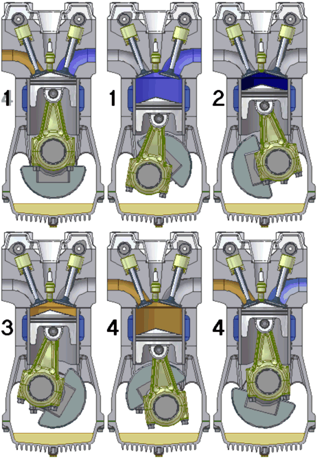
                Đây là trich đoạn của một bài viết về động cơ 4 thì:

                Các thì trong một động cơ pít tông đẩy 4 thì

                1. Trong thì thứ nhất (nạp – van nạp mở, van xả đóng) hỗn hợp không khí và nhiên liệu được "nạp" vào xy lanh trong lúc pít tông chuyển động đi xuống.
                2. Trong thì thứ hai (nén – hai van đều đóng) pít tông nén hỗn hợp khí trong xy lanh khi chuyển động đi lên. Ở cuối thì thứ hai (pít tông ở tại điểm chết trên) hỗn hợp khí được đốt, trong động cơ xăng bằng bộ phận đánh lửa, trong động cơ diesel bằng cách tự bốc cháy.
                3. Trong thì thứ ba (tạo công – các van vẫn tiếp tục được đóng) hỗn hợp khí được đốt cháy. Vì nhiệt độ tăng dẫn đến áp suất của hỗn hợp khí tăng và làm cho pít tông chuyển động đi xuống. Chuyển động tịnh tiến của pít tông được chuyển bằng tay biên đến trục khuỷu và được biến đổi thành chuyển động quay.
                4. Trong thì thứ tư (xả - van nạp đóng, van xả mở) pít tông chuyển động đi lên đẩy khí từ trong pít tông qua ống xả thải ra môi trường.


                Theo như khuyến cáo của một số nhà chế tạo thì góc đánh lửa sớm bao nhiêu sẽ tùy thuộc vào việc thiết kế động cơ. Đồng thời ứng với mỗi thiết kế, người ta sẽ yêu cầu sử dụng xăng có chỉ số Octal tối thiểu.

                Dưới đây là trích đoạn của hãng Piagio, hãng thiết kế chiếc Vespa nổi tiếng:

                2.3. Các yếu tố ảnh hưởng đến trị số tối thiểu của động cơ bao gồm:
                - Kết cấu buồng đốt: các động cơ hiện đại được thiết kế có các rãnh xoắn để tăng hiệu suất và giảm trị số octane yêu cầu.
                - Tỷ lệ nhiên liệu: không khí: thay đổi tỷ lệ nhiên liệu/ không khí làm thay đổi yêu cầu về trị số octane và làm giảm hiệu suất của động cơ.
                - Nhiệt độ môi trường: nhiệt độ càng cao yêu cầu về trị số octane càng tăng. Tuy nhiên, mức độ ảnh hưởng này không đáng kể.
                - Độ cao: càng cao so với mực nước biển, yêu cầu trị số octane càng giảm.
                -Độ ẩm: tăng độ ẩm giảm yêu cầu trị số octane. Tuy nhiên, ảnh hưởng đến nhiệt độ và độ ẩm không lớn.
                -Góc đánh lửa: góc đánh lửa càng sớm, yêu cầu trị số octane càng cao. Ví dụ, đối với một động cơ khuyến cáo góc đánh lửa là 6˚ (trước điểm chết trên), yêu cầu trị số octane là 93, nếu góc đánh lửa trễ (???) là 4 ˚ thì trị số octane yêu cầu là 91, còn nếu sớm lên 8˚ thì yêu cầu trị số octane là 96.

                ......


                Thông thường, với xe đánh lửa bằng vis lửa, góc đánh lửa là cố định, và có thể điều chỉnh bằng vị trí của vis lửa. Xe đánh lửa bằng CDI đơn giản, thì góc đánh lửa cũng cố định, phụ thuộc vào vị trí của cuộn dây pickup. Còn các xe đánh lửa bằng CDI có điều chỉnh góc, thì phạm vi điều chỉnh cũng trong khoảng vài độ đến 15 độ.
                Nhóc thích nghịch điện,
                Nhóc thích xì păm,
                Nhóc thích trêu mấy anh.
                Hi hi.

                Comment


                • #9
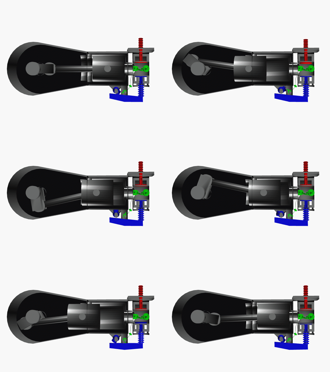
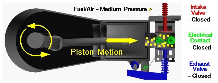
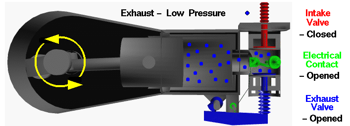
                  Dưới đây là 1 đoạn Nhóc copy của NASA, mô tả một cái động cơ đốt trong được sử dụng trong chiếc phi cơ đầu tiên do anh em nhà Writes chế tạo. Nguyên lý này cho đến nay chưa thay đổi gì.


                  This is an animated computer drawing of one cylinder of the Wright brothers' 1903 aircraft engine. This engine powered the first, heavier than air, self-propelled, maneuverable, piloted aircraft; the Wright 1903 Flyer. The engine consisted of four cylinders like the one shown above, with each piston connected to a common crankshaft. The crankshaft was connected to two counter-rotating propellers which produced the thrust necessary to overcome the drag of the aircraft.

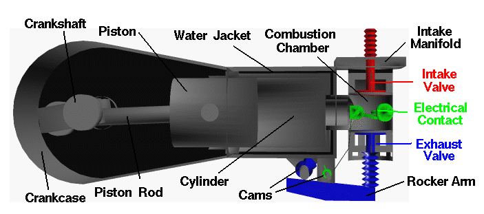
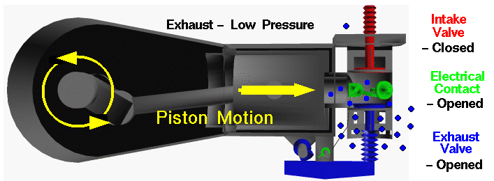
                  The brothers' design is very simple by today's standards, so it is a good engine for students to study to learn the fundamentals of engine operation. This type of internal combustion engine is called a four-stroke engine because there are four movements, or strokes, of the piston before the entire engine firing sequence is repeated. The four strokes are described below with some still figures. In the animation and in all the figures, we have colored the fuel/air intake system red, the electrical system green, and the exhaust system blue. We also represent the fuel/air mixture and the exhaust gases by small colored balls to show how these gases move through the engine. Since we will be referring to the movement of various engine parts, here is a figure showing the names of the parts:


                  Intake Stroke

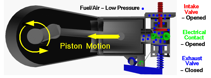
                  The engine cycle begins with the intake stroke as the piston is pulled towards the crankshaft (to the left in the figure).


                  The intake valve is open, and fuel and air are drawn past the valve and into the combustion chamber and cylinder from the intake manifold located on top of the combustion chamber. The exhaust valve is closed and the electrical contact switch is open. The fuel/air mixture is at a relatively low pressure (near atmospheric) and is colored blue in this figure. At the end of the intake stroke, the piston is located at the far left and begins to move back towards the right.


                  The cylinder and combustion chamber are full of the low pressure fuel/air mixture and, as the piston begins to move to the right, the intake valve closes.

                  Historical note - The opening and closing of the intake valve of the Wright 1903 engine was termed "automatic" by the brothers. It relies on the slightly lower pressure within in the cylinder during the intake stroke to overcome the strength of the spring holding the valve shut. Modern internal combustion engines do not work this way, but use cams and rocker arms like the brothers' exhaust system. Cams and rocker arms provide better control and timing of the opening and closing of the valves.

                  Compression Stroke

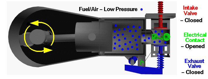
                  With both valves closed, the combination of the cylinder and combustion chamber form a completely closed vessel containing the fuel/air mixture. As the piston is pushed to the right, the volume is reduced and the fuel/air mixture is compressed during the compression stroke.


                  During the compression, no heat is transferred to the fuel/air mixture. As the volume is decreased because of the piston's motion, the pressure in the gas is increased, as described by the laws of thermodynamics. In the figure, the mixture has been colored yellow to denote a moderate increase in pressure. To produce the increased pressure, we have to do work on the mixture, just as you have to do work to inflate a bicycle tire using a pump. During the compression stroke, the electrical contact is kept opened. When the volume is the smallest, and the pressure the highest as shown in the figure, the contact is closed, and a current of electricity flows through the plug.

                  Power Stroke

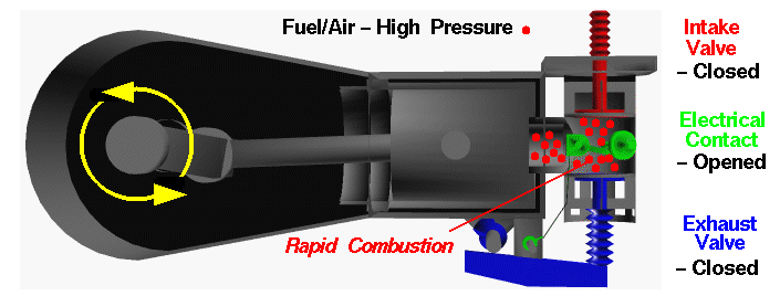
                  At the beginning of the power stroke, the electrical contact is opened. The sudden opening of the contact produces a spark in the combustion chamber which ignites the fuel/air mixture. Rapid combustion of the fuel releases heat, and produces exhaust gases in the combustion chamber.


                  Because the intake and exhaust valves are closed, the combustion of the fuel takes place in a totally enclosed (and nearly constant volume) vessel. The combustion increases the temperature of the exhaust gases, any residual air in the combustion chamber, and the combustion chamber itself. From the ideal gas law, the increased temperature of the gases also produces an increased pressure in the combustion chamber. We have colored the gases red in the figure to denote the high pressure. The high pressure of the gases acting on the face of the piston cause the piston to move to the left which initiates the power stroke.


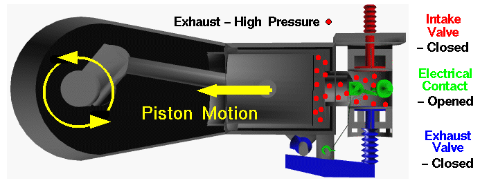
                  Unlike the compression stroke, the hot gas does work on the piston during the power stroke. The force on the piston is transmitted by the piston rod to the crankshaft, where the linear motion of the piston is converted to angular motion of the crankshaft. The work done on the piston is then used to turn the shaft, and the propellers, and to compress the gases in the neighboring cylinder's compression stroke. Having produced the igniting spark, the electrical contact remains opened.

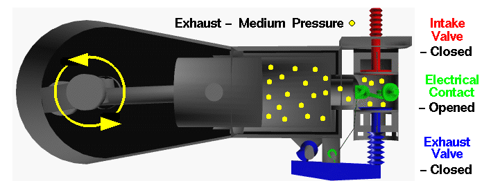
                  During the power stroke, the volume occupied by the gases is increased because of the piston motion and no heat is transferred to the fuel/air mixture. As the volume is increased because of the piston's motion, the pressure and temperature of the gas are decreased. We have colored the exhaust "molecules" yellow to denote a moderate amount of pressure at the end of the power stroke.


                  istorical note - The method of producing the electrical spark used by the Wright brothers is called a "make and break" connection. There are moving parts located inside the combustion chamber. Modern internal combustion engines do not use this method, but instead use a spark plug to produce the ignition spark. A spark plug has no moving parts, which is much safer than the method used by the brothers.

                  Exhaust Stroke

                  At the end of the power stroke, the piston is located at the far left. Heat that is left over from the power stroke is now transferred to the water in the water jacket until the pressure approaches atmospheric pressure. The exhaust valve is then opened by the cam pushing on the rocker arm to begin the exhaust stroke.


                  The purpose of the exhaust stroke is to clear the cylinder of the spent exhaust in preparation for another ignition cycle. As the exhaust stroke begins, the cylinder and combustion chamber are full of exhaust products at low pressure (colored blue on the figure above.) Because the exhaust valve is open, the exhaust gas is pushed past the valve and exits the engine. The intake valve is closed and the electrical contact is open during this movement of the piston.


                  At the end of the exhaust stroke, the exhaust valve is closed and the engine begins another intake stroke.

                  Historical note - The exhaust system used by the Wright brothers caused the hot exhaust to exit each cylinder independently ... right next to the pilot. This engine was very loud as well. Modern automobiles collect the exhaust from all of the cylinders into an exhaust manifold (just like the intake manifold used by the brothers). The exhaust manifold passes the exhaust to the catalytic converter to remove dangerous gases, and then through the muffler to keep it quiet, and finally out the exhaust pipe.

                  You should now be able to make some sense from the animation at the top of this page. Notice that the crankshaft makes two revolutions for every one revolution of the cams. This motion is controlled by the timing chain. Also notice how the cam moves the exhaust valve at just the right time and how quickly the intake valve opens after the exhaust valve is closed. In real engine operation, the exhaust stroke can not push all of the exhaust out of the cylinder, so a real engine doesn't perform as well as the ideal engine described on this page. As the engine runs and heats up, the performance changes. Modern automobile engines adjust the fuel/air ratio with computer controlled fuel injectors to maintain high performance. The brothers just had to watch the horsepower of their engine drop from about 16 horsepower when the engine was first started to about 12 horsepower when it was running hot.
                  Nhóc thích nghịch điện,
                  Nhóc thích xì păm,
                  Nhóc thích trêu mấy anh.
                  Hi hi.

                  Comment


                  • #10
                    Nguyên văn bởi cô nhóc Xem bài viết
                    Dưới đây là 1 đoạn Nhóc copy của NASA, mô tả một cái động cơ đốt trong được sử dụng trong chiếc phi cơ đầu tiên do anh em nhà Writes chế tạo. Nguyên lý này cho đến nay chưa thay đổi gì.


                    This is an animated computer drawing of one cylinder of the Wright brothers' 1903 aircraft engine. This engine powered the first, heavier than air, self-propelled, maneuverable, piloted aircraft; the Wright 1903 Flyer. The engine consisted of four cylinders like the one shown above, with each piston connected to a common crankshaft. The crankshaft was connected to two counter-rotating propellers which produced the thrust necessary to overcome the drag of the aircraft.

                    The brothers' design is very simple by today's standards, so it is a good engine for students to study to learn the fundamentals of engine operation. This type of internal combustion engine is called a four-stroke engine because there are four movements, or strokes, of the piston before the entire engine firing sequence is repeated. The four strokes are described below with some still figures. In the animation and in all the figures, we have colored the fuel/air intake system red, the electrical system green, and the exhaust system blue. We also represent the fuel/air mixture and the exhaust gases by small colored balls to show how these gases move through the engine. Since we will be referring to the movement of various engine parts, here is a figure showing the names of the parts:


                    Intake Stroke

                    The engine cycle begins with the intake stroke as the piston is pulled towards the crankshaft (to the left in the figure).


                    The intake valve is open, and fuel and air are drawn past the valve and into the combustion chamber and cylinder from the intake manifold located on top of the combustion chamber. The exhaust valve is closed and the electrical contact switch is open. The fuel/air mixture is at a relatively low pressure (near atmospheric) and is colored blue in this figure. At the end of the intake stroke, the piston is located at the far left and begins to move back towards the right.


                    The cylinder and combustion chamber are full of the low pressure fuel/air mixture and, as the piston begins to move to the right, the intake valve closes.

                    Historical note - The opening and closing of the intake valve of the Wright 1903 engine was termed "automatic" by the brothers. It relies on the slightly lower pressure within in the cylinder during the intake stroke to overcome the strength of the spring holding the valve shut. Modern internal combustion engines do not work this way, but use cams and rocker arms like the brothers' exhaust system. Cams and rocker arms provide better control and timing of the opening and closing of the valves.

                    Compression Stroke

                    With both valves closed, the combination of the cylinder and combustion chamber form a completely closed vessel containing the fuel/air mixture. As the piston is pushed to the right, the volume is reduced and the fuel/air mixture is compressed during the compression stroke.


                    During the compression, no heat is transferred to the fuel/air mixture. As the volume is decreased because of the piston's motion, the pressure in the gas is increased, as described by the laws of thermodynamics. In the figure, the mixture has been colored yellow to denote a moderate increase in pressure. To produce the increased pressure, we have to do work on the mixture, just as you have to do work to inflate a bicycle tire using a pump. During the compression stroke, the electrical contact is kept opened. When the volume is the smallest, and the pressure the highest as shown in the figure, the contact is closed, and a current of electricity flows through the plug.

                    Power Stroke

                    At the beginning of the power stroke, the electrical contact is opened. The sudden opening of the contact produces a spark in the combustion chamber which ignites the fuel/air mixture. Rapid combustion of the fuel releases heat, and produces exhaust gases in the combustion chamber.


                    Because the intake and exhaust valves are closed, the combustion of the fuel takes place in a totally enclosed (and nearly constant volume) vessel. The combustion increases the temperature of the exhaust gases, any residual air in the combustion chamber, and the combustion chamber itself. From the ideal gas law, the increased temperature of the gases also produces an increased pressure in the combustion chamber. We have colored the gases red in the figure to denote the high pressure. The high pressure of the gases acting on the face of the piston cause the piston to move to the left which initiates the power stroke.


                    Unlike the compression stroke, the hot gas does work on the piston during the power stroke. The force on the piston is transmitted by the piston rod to the crankshaft, where the linear motion of the piston is converted to angular motion of the crankshaft. The work done on the piston is then used to turn the shaft, and the propellers, and to compress the gases in the neighboring cylinder's compression stroke. Having produced the igniting spark, the electrical contact remains opened.

                    During the power stroke, the volume occupied by the gases is increased because of the piston motion and no heat is transferred to the fuel/air mixture. As the volume is increased because of the piston's motion, the pressure and temperature of the gas are decreased. We have colored the exhaust "molecules" yellow to denote a moderate amount of pressure at the end of the power stroke.


                    istorical note - The method of producing the electrical spark used by the Wright brothers is called a "make and break" connection. There are moving parts located inside the combustion chamber. Modern internal combustion engines do not use this method, but instead use a spark plug to produce the ignition spark. A spark plug has no moving parts, which is much safer than the method used by the brothers.

                    Exhaust Stroke

                    At the end of the power stroke, the piston is located at the far left. Heat that is left over from the power stroke is now transferred to the water in the water jacket until the pressure approaches atmospheric pressure. The exhaust valve is then opened by the cam pushing on the rocker arm to begin the exhaust stroke.


                    The purpose of the exhaust stroke is to clear the cylinder of the spent exhaust in preparation for another ignition cycle. As the exhaust stroke begins, the cylinder and combustion chamber are full of exhaust products at low pressure (colored blue on the figure above.) Because the exhaust valve is open, the exhaust gas is pushed past the valve and exits the engine. The intake valve is closed and the electrical contact is open during this movement of the piston.


                    At the end of the exhaust stroke, the exhaust valve is closed and the engine begins another intake stroke.

                    Historical note - The exhaust system used by the Wright brothers caused the hot exhaust to exit each cylinder independently ... right next to the pilot. This engine was very loud as well. Modern automobiles collect the exhaust from all of the cylinders into an exhaust manifold (just like the intake manifold used by the brothers). The exhaust manifold passes the exhaust to the catalytic converter to remove dangerous gases, and then through the muffler to keep it quiet, and finally out the exhaust pipe.

                    You should now be able to make some sense from the animation at the top of this page. Notice that the crankshaft makes two revolutions for every one revolution of the cams. This motion is controlled by the timing chain. Also notice how the cam moves the exhaust valve at just the right time and how quickly the intake valve opens after the exhaust valve is closed. In real engine operation, the exhaust stroke can not push all of the exhaust out of the cylinder, so a real engine doesn't perform as well as the ideal engine described on this page. As the engine runs and heats up, the performance changes. Modern automobile engines adjust the fuel/air ratio with computer controlled fuel injectors to maintain high performance. The brothers just had to watch the horsepower of their engine drop from about 16 horsepower when the engine was first started to about 12 horsepower when it was running hot.
                    theo tài liệu củ về xăng fa chì thì tốc độ cháy lan của xăng là khoảng 30m/s
                    nên khi thiết kế một động cơ đốt trong nhà sx người ta tính ra góc đánh lửa,
                    và còn tùy thuộc vào DT xy lanh đường kính piston tốc độ vòng quay,cho
                    nên có thể từ 4-20 độ . còn về xăng mới thì tôi chưa cập nhât.
                    xin lổi qýu vị mình pót bài nó chạy đi tầm bậy làm xả rát diển đàn
                    mình xin lổi và xin viết lại

                    Comment


                    • #11
                      Nguyên văn bởi vinhthanh Xem bài viết
                      theo tôi Bác Dinh van nên chịu khó tự mình tìm hiểu về nguyên lý ĐC đốt trong trên sách vở có bán đầy ngoài hiệu sách.chứ không nên tham khảo qua
                      cái ông thợ honda cà là mèn nào đó .vì sự cháy nổ trong DC dốt trong là fải cháy tức thì không thể kéo dài trên đường đi xuống của pistone.không những
                      làm mất CS mà còn gây nóng DC kéo dài lửa ra ngoài ống xả đó...
                      chúc vui
                      Mình không chuyên vầ cái này . Tuy vậy nói như cậu chắc chắn người ta không cần huy động đến cả Pic hay VXL vào đây
                      Với cả trên thế giới này làm gì có cái gì là .... Tức thì
                      Người cho rằng một sự việc xảy ra tức thì , là người xa rời thực tiễn rồi đó
                      Chuyên làm các mạch điện tử bí hiểm và kỳ quặc .
                      nguyendinhvan1968@gmail.com

                      Mobil : 0903 252 168 Chỉ gọi từ 09 giờ đến 17 giờ . Từ 18 giờ ngoài vùng phủ sóng

                      Comment


                      • #12
                        Đúng đó bác ạ trong động cơ nó ko cháy tức thỉ dâu mà cần qua một công đoạn lan truyền màng lửa. bởi thế mới sinhn ra góc đánh lửa sớm. và có thể huy động cả VXL vào nứa đó . Chắc bác ko biết ECU trên Ô tô nhỉ loại CDI nó là như vậy đó.

                        Comment


                        • #13
                          Xin chào tất cả các bạn mình là mem mới tin lò dò trên mạng thấy trang này hay quá, mình có vấn đề thắc mắc có gì các bạn chỉ giáo giúp nhé, lần đầu tiên vô 4room có gì các bạn bỏ qua cho .

                          |

                          Comment


                          • #14
                            Các bạn có thể cho mình cái mạch regu của số 9 trong hình có mã là SH765AA 5N222 công suất của nó là bao nhiêu?, và sơ đồ chứ năng chân CDI của số 10 .

                            Rất cám ơn các bạn giúp nhé
                            |

                            Comment


                            • #15
                              Theo như mình để ý thì hình như tác dụng chỉ thấy rõ khi chạy đường trường mà thôi nhưng không viết đối với các loại xe tay ga bơm xăng tự độ thì sao các bác?

                              Comment

                              Về tác giả

                              Collapse

                              nguyendinhvan Tìm hiểu thêm về nguyendinhvan

                              Bài viết mới nhất

                              Collapse

                              Đang tải...
                              X